Table of Contents
MODEM/PHONE LINE SWITCH
Here's the plight of many a BBS SysOp:
In your 'data center' you have you BBS happily running in a cramped little corner, with bunches of wires and whirring fans, but little room to sit at the console. Elsewhere in the room you have one or more other computers that you either connect to the BBS locally (modem to modem) or to the outside world. Reconfiguring your local wires to connect to the BBS or outside usually means plugging and unpluging wires between various modems and the wall outlet, which can be a mess and a pain to keep it all right in your head.
This project will present a more elegant solution.
the Null-Modem/Line Switch
Basically what the switch does is let each computer in the chain of phone wire, access either line 1 (the inside red/green pair of a phone wire) or line 2 (the outside yellow/black pair of a phone wire) and also disconnect line 1 from the wall (while still preserving line 2 for any outside computer access) so the computers in the chain can connect together locally or outside.
BUILDING IT
The parts for this project are relatively simple to locate and building it is small task with a bit of soldering and some drilling/filing to make a nice project box for the circuit.
Parts List:
- Single Position Double Throw Switch
- Double Position Double Throw Switch
- Phone wire with RJ-11 modular plug on one end
- RJ-11 phone jack doubler (plug on one end, two jacks on the other)
- Panel or small box to mount the parts (small box recommended)
A visit to a 'dollar store' (for the phone wire and doubler and maybe the box) and a Radio Shack (for the switches) should get you all the parts for under $7 a unit.
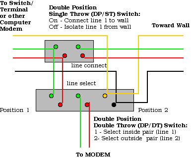
Here is the diagram for how to wire a switch box
 (yeah the circuit looks easy, but it sure took a while for me to figure it out!)
Here is a picture of a completed unit (I found an outlet tripler, the middle jack is to the modem, one on the right is toward the wall and the one on the left toward the next modem/switch box down the line. I arranged the switches so it made sese when you plugged in the wires (the → symbol next to the SPDT switch is ON, or connect line 1 toward wall, the numbers 1 and 2 indicate selecting lines 1 and 2 respectively.)
Here is a picture of the underside which gives a good view of the wiring I made, (remember this is flipped over so think the other way from what you saw above)
USING IT
Example of how it all works (this is a three computer environment; a Commodore BBS, a Mac and a Commodore 64 - who could want anything more? Any combination of computer will work, just needs a modem with a modular wire connector):
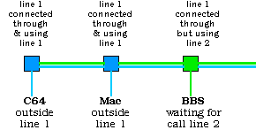
 Here is the 'normal' setup for a BBS sysop, the BBS is connected to 'the BBS line' (line 2) to get incoming calls from users, and line 1 is available for the other two computers in the room to access (of course not at the same time, that would be nearly impossible.):
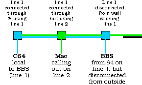
 Now with a couple of flips of the switch boxes, the 64 can gain acces the BBS directly without unplugging the phone wire, and the Mac in the middle can still call out (on line 2):
The Mac's box was changed to line 2 and the BBS to line 1, and the line 1 access to the wall was disabled at the BBS too. Cool, eh? You can also link the Mac and 64 together or the Mac and BBS and still have line 2 access with the other machine…
SETTING UP FOR NULL-MODEM CONNECTION
Besides the wiring you may need to do some configuring of your terminal and/or modem to make a successful null-modem connection.
- Both Terminals or Terminal/BBS need to be set for compatible speeds, usually the BBS has auto speed settings, but many terminals don't so make sure they are set for the maximum to slowest modem you are using in your connection allows.
- On some high speed (14.4k+) modems you may have to disable high speed compression to get a connection; if you need to use it enter AT&Q6 (for Hays compatible modems) to disable high speed compresion (when you reset the modem it will return to normal operation)
- If modem to modem, st both terminals to half-duplex or local echo, This seems to work more reliably in a null-modem setting than using full duplex.
- One terminal will 'dial' and the other will 'answer', on the dialing terminal you may need to disable the 'detect dial tone' feature, this is done by entering ATX3 on Hayes command compatible modems. To dial out, the 'calling terminal would enter ATDT and the answering computer would nee to have ATA entered shortly after that. You should hear those familiar modem connection sounds and you will then be connected.
- If you are connecting locally to a BBS, most BBS programs have an 'answer phone' or 'force answer' control key to get the BBS to pick up without hearing a ring from its modem.
If you have never done this before you might want to test this out before building this project by just stinging the modems together with a wire (both connect to the line port) and testing/practising especially to determine if the BBS has a 'force answer' feature.