Table of Contents
Commodore 8-bit Networking Idea
Updated 08/02/2006
HISTORY
Part of my work on re-doing Flash Attack is implementating a 6-player version, the original flash cable is only designed for two computers and may prove problematic for six computers, at some point I ran across an article in the March 1988 issue of Trasnsactor Magazine called Interfacing 2 64s. This concept uses the built-in 'serial ports' of the 6526 chips (not the RS-232, this is all in hardware)
I could see with a slight adjustment this could be used as a basic networking topology which would be less cumbersome than using all the parallel i/0 pins.
(Note another excellent write up on the 6522/6526) can be found in the book “the PET Revealed” by Nick Hampshire.
Interfacing:
The Commodore 64 and others in the 8-bit line are equipped with two 6522 Versatile Interface Adapters, which each provide a an easy to use serial communications 'port' which when configured properly can transmit a byte of data from a register to another serial port.
By utilizing these ports, one for input, and the other for output you could send data between one or more other computers with similar ports.
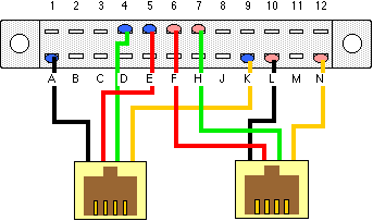
 Example Pinout for such a port. This plan uses a 1 plug to 2 outlet phone line splitter and a Commodore edgeboard connector, which allows for easy connection of common 4-wire phone leads with RJ11 plugs.
Diagram above is looking at the connection side of the edge connector and the outlet side of the RJ 11 jacks
| Pin | Description | data direction |
|---|---|---|
| 4 | Serial Port Counter from CIA #1 | [in] |
| 5 | Serial Port from CIA #1 | [in] |
| 6 | Serial Port Counter from CIA # 2 | [out] |
| 7 | Serial Port from CIA # 2 | [out] |
| A | Ground | [in] |
| K | Parallel Port B Bit # 6* | [in] |
| L | Parallel Port B Bit # 7* | [out] |
| N | Ground | [out] |
* this 1-bit data connection is not really needed for this project but may come in handy later, or may serve as a minor reverse direction connection.
The reversed order of the input and output wires is necessary if we are to use standard phone wire un-modified, as there is a half-turn from end to end.
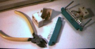
Photo of parts needed:
 Modular splitter is popped apart to show wires,which would be cut as close to the plug-end to allow maximum length, connector on right is a complete soldered assembly (sans hood), the long machine screws offer an alternative gripping surface to plug/in and remove the connectors (use #6-32 x 1.5“ machine screws)
The edgeboard connectors can be purchased from DigiKey Corporation
Part # EDC307240-ND ( Edgeboard Connector, 24 contact, .156” pitch, solder-eye connectors, .200“ gap) - $3.47 ea or 10 for $30.80…
connectors
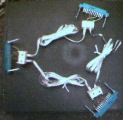
 And photo of three connectors with wire showing what a three node configuration would look like:
Presently this is where I am in my project. (still have a ways to go)
but I do have some notes for the next phases:
COMMUNICATION PROTOCOL
Here is the assembly I have drafted out based on the article in the march 1988 Transactor
Sample serial communication 6502 assembly
SEND DATA:

SENDSETUP     LDA #%01111111
              STA $DD0D        ;clear all interrupts
              LDA LDA#$04
              STA $DD04        ;set lo-byte of timer to high rate
              LDA #$00
              STA $DD05        ;set hi-byte of timer to high rate
              LDA #%01000000
              STA $DD0E        ;set up timer control register
              SEI              ;set interrupt disable
SENDLOOP      LDA [DATA]
              STA $DD0C        ;send data
              LDA #%00001000
WAITTILLSENT  BIT $DD0D
              BEQ WAITTILLSENT ;still sending
              [MORE DATA TO SEND?]
              [IF SO,] JMP/BEQ TO SENDLOOP
SENDFINISH    CLI
              RTS


RECEIVE DATA:

RECSETUP      LDA #%01111111
              STA $DD0D        ;clear all interrupts
              LDA $DC0E
              AND #$10111111
              STA $DC0E        ;serial port input at external clock rate...
WAITFORDATA   LDA $DC0D
              AND #%00001000
              BEQ WAITFORDATA  ;wait for 'data arrived' bit
              LDA $DC0C        ;get received byte
              [STORE RECIEVED BYTE]
              [MORE DATA TO RECEIVE?]
              [IF SO,] JMP/BEQ WAITFORDATA
RECFINISH     LDA #%10000001
              STA $DC0D        ;re-enable interrupts
              RTS
Example use - Multiplayer Game
Now my project is for an arcade style game, so the process order is important to maximize timing; nodes would be number from 0 to the end the order to be determined by first-transmit-first-node… once in play each node would transmit each node's 'move data' around the loop, after which the next node would then get another turn to transmit it's move.
The best process would be to have the nodes processing the bulk of the turns as simultaneously as possible to keep from having additional nodes slowing down the game play
Example process (if this mode was starting the loop):
- Computer process the joystick or keyboard input as quick 'n dirty as possible
- Transmit its 'move data' down line
- Resolve its action (move, shoot, whatever)
- increment 'active node' counter (X)
- Wait for node X's move data
- send it down line to next computer
- Resolve that player's action
- Increment node counter (X), if it's my turn again, go to step 1, if not go to 5
General Purpose Networking
Here are some later notes on possible protocol for a round-robin networking scheme for any application using the cable design.
This time I went beyond the game approach and thought of what would work for a mixed working environment, some computers transferring, others not, long downloads between several nodes, etc.
Data should be in packets, to make the stuff more manageable (and give the non-net active systems some processing time.) I figure a variable length packet of 1 to 256 characters would be best (makes data easy to send/receive and move by a simple increment loop), also by making it at least 254 bytes makes moving disk blocks or memory pages less complicated.) preceding a packet would be three bytes, identifying the destination node, the source node and packet data length: 0=1 byte to 255=256 bytes.
Sample structure (four byte packet from node 1 to 5):
| 005 | 003 | 001 | 000 | 255 | 034 | 001 |
|---|---|---|---|---|---|---|
| Desitnation | Length | Source Node | data | data | data | data |
The reason for the length isn't the last header byte will be apparent later on. 
Now as I thought before, we would want to bunch up the packets going downline so each machine will need a 'transfer buffer', I figure for a basic start 5180 bytes or so, this would hold up to 20 full 256 byte packets - keeping it under 8k makes it a good candidate for 'under ROM' memory (since the transfer routine would not be based on the kernal or BASIC it is a good place to keep temp data, maybe even put some of the transfer code there too. Also we don't want it too big because we need to 'garbage collect' any unclaimed packets after transfer outs.
Next up would be the transfer protocol
(I'm kinda stuck on the mechanics, will worry about basic interfacing later…)
So, our transfer program would be an IRQ routine, there would be three triggers to activate it:
- incomming data from upline
- request to send locally
- log-jam resolved (this is the 'later')
So the process would be:
IRQ routine:
- Check for data waiting signal (either use the 'data arrived bit' or use PA6 as a flag from upline)
- Check for Local Send Request or packets to be sent count
- Verify absence of logjam
[if either of the first two are set and the second is clear, go to the transfer routine]
Transfer Routine
[transfer-recieve]
- receive packet destination from upline (clear PA6, they do too - once it is sent)
- is source “$ff”? yes, end / if incoming, go to [8]
- receive packet length from upline (compare with buffer pointer, space left?, if no, set PA6, log-jam)
- receive packet source (this gives the sending computer a bit of time before checking it's PA7 for a logjam)
- logjam? if yes, go to send [8].
- If everything is ok, get data packet
- go to 1
[transfer-send]
- is there a logjam ahead? yes, go to [17]
- send packet dest (and clear PA7)
- send packet length
- send source node#
- check PA7 - log jam? if yes, go to [17]
- everything ok, send packet
- last packet?
- yes, then send $ff and go to [17]
- no, go to [8]
- update local status registers, garbage collect and go back to irq wait.
The local registers would be something like:
- node#
- max # nodes
- buffer full/log-jam
- free space?
- waiting data (count?)
I thought about letting any small packets sift through a logjam, but if you bunched up a file transfer theoretically the end of the file could arrive before the source header, so if the oldest packet doesn't fit no others should go past either.
There are probably a couple holes, it needs some checks for local packets, maybe a 'receive buffer' for incomming local stuff, outgoing counters, a 'to all' broadcast packet ID, etc. but this is basically what I envision as the basic data-mover.
